

PRODUCTS
- Aerial Bundled Cables
- Airport Cables
- Automotive Cables
- Alarm & Audio & Electronic Cables
- Belden Equivalent Cables
- Bus Cables
- Cable Glands
- Cables for Oil Industry
- Coaxial Cables
- Composite Cables
- Control Cables
- Data Cable
- Elevator Cables
- Fiber Optic Cables
- Fire Resisting Cable(Fireflix)
- Fire Retardant Cable(FIRETOX)
- Flame Retardant Cable (FIREGUARD)
- Flexible Cables
- Heat Detection Cables
- High Temperature Cables
- Highway Cables
- Industrial Cables
- Instrumentation Cables
- Lan Cables
- Marine Cable
- NEK606 Water Blocked Offshore & Marine Cables
- IEC60092 STANDARD Offshore & Marine Cables
- BS 6883&BS7917 STANDARD Offshore & Marine Cables
- UKOOA Offshore & Marine cables
- VG 95218 Navy Cables
- Mining Cables
- Airframe Wire
- Marine, OIL,GAS & Petrochemical Cables
- Power Cables
- Railway Cables
- Robotics
- Rolling Stock Cables
- Rubber & Crane Cables
- Security Cables
- Special Cables
- Spiral Cables
- Telephone Cables
- Thermocouple Cables
- BS 5308 Cable
- PAS 5308 Cable
- BS 5467 Cable
- BS 6724 Cable
- BS 6346 Cable
- BS 7211 Cable
- IEC 60502-1 Cable
HOT PRODUCTS

APPLICATIONS
|
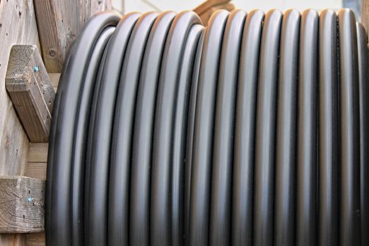
NEK606 Water Blocked
Offshore & Marine Cables
Water Blocked P4 or P4/P11 RFOU/TFOU 8.7/15KV
Applications
-
These P4 or P4/P11 RFOU/TFOU 8.7/15KV NEK606 Water Blocked Offshore Marine cables are partially water blocked, flame retardant, low smoke, halogen free and mud resistant, used for fixed installation for medium voltage power.
Standards
-
IEC 60092-353 IEC 60092-351 IEC 60092-359 IEC 60332-1 IEC 60332-3-22 IEC 60754-1,2 IEC 61034-1,2 NEK 606:2004 VG 95218 part 29

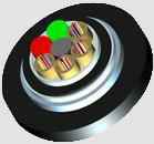
Construction
-
l Conductors: Circular tinned annealed stranded copper to IEC 60228 class 2.
l Conductor Screen: Semi conducting material.
l Insulation: Halogen-free EPR. XLPE can be offered as an option (for TFOU cable).
l Insulation Screen: Semi conducting material and tinned copper wire braid.
l Filler: Water blocking fillers, if required.
l Bedding: Halogen free compound, PETP wrapping tape will be applied over the bedding, if required.
l Armour: Tinned copper wire braid, PETP wrapping tape will be applied over the braiding, if required.
l Water Blocking Elements: Water blocking tape and strings for providing longitudinal water tightness.
l Inner Sheath: Halogen free thermosetting compound, SHF2 (for TYPE P4), or halogen free mud resistant thermosetting compound, SHF MUD (for TYPE P4/P11), coloured red.
l Outer Sheath: Polyurethane for providing transversal water tightness, PE is optional,but can not meet low smoke standard.
Electrical Characteristics
-
Nominal Cross Section Area mm2 25 35 50 70 95 120 Nominal Conductor Diameter mm 6.5 7.4 8.7 10.3 12.2 13.8 Maximum DC Resistant@20˚C O/km 0.734 0.529 0.391 0.27 0.195 0.154 Continuous Current Rating@45˚C1 Core A 127 157 196 242 293 339 Continuous Current Rating@45˚C3 Core A 89 110 137 169 205 237 Short Circuit Current 1s A 3580 5010 7150 10020 13590 17170 Operating Voltage KV 8.7/15 8.7/15 8.7/15 8.7/15 8.7/15 8.7/15
-
Nominal Cross Section Area mm2 150 185 240 300 400 500 630 Nominal Conductor Diameter mm 15.1 17.0 19.6 21.9 24.5 27.5 32.3 Maximum DC Resistant@20˚C O/km 0.126 0.1 0.0762 0.0607 0.0475 0.0369 0.0286 Continuous Current Rating@45˚C1 Core A 389 444 522 601 690 780 890 Continuous Current Rating@45˚C3 Core A 272 311 365 421 483 546 623 Short Circuit Current 1s A 21460 26470 34340 42930 57230 71540 90140 Operating Voltage KV 8.7/15 8.7/15 8.7/15 8.7/15 8.7/15 8.7/15 8.7/15
Ambient Temperature Correction Factors
-
Ambient Temperature Correction Factors 35 40 45 50 55 60 65 70 75 80 Rating Factor 1.1 1.05 1.0 0.94 0.88 0.82 0.74 0.67 0.58 0.47
Mechanical and Thermal Properties
-
Bending Radius :15×OD (during installation); 9×OD (fixed installed).
-
Temperature Range : -20˚C ~ +90˚C.
Dimensions and Weight
| Construction No. of cores×Cross section (mm2) | Nominal Insulation Thickness mm | Nominal Bedding Thickness mm | Nominal Inner Sheath Thickness mm | Nominal Outer Sheath Thickness mm | Nominal Overall Diameter mm | Nominal Weight kg/km |
|---|---|---|---|---|---|---|
| 1×150 | 4.5 | 2 | 1.5 | 1.4 | 40.9±2 | 3087 |
| 1×185 | 4.5 | 2 | 1.5 | 1.4 | 43.4±2 | 3722 |
| 1×240 | 4.5 | 2.1 | 1.6 | 1.6 | 46.6±2 | 4431 |
| 1×300 | 4.5 | 2.2 | 1.7 | 1.6 | 49.5±2 | 5324 |
| 1×400 | 4.5 | 2.4 | 1.8 | 1.6 | 53.4±2 | 6048 |
| 1×500 | 4.5 | 2.5 | 1.8 | 1.6 | 56.8±2 | 7224 |
| 1×630 | 4.5 | 2.6 | 1.9 | 1.6 | 61.1±2 | 8883 |
| 3×25 | 4.5 | 2.6 | 1.9 | 1.2 | 57.7±2 | 4961 |
| 3×35 | 4.5 | 2.7 | 2 | 1.2 | 59.9±2 | 5476 |
| 3×50 | 4.5 | 2.8 | 2 | 1.2 | 63.0±2 | 6258 |
| 3×70 | 4.5 | 2.9 | 2.1 | 1.2 | 66.8±2 | 7387 |
| 3×95 | 4.5 | 3.1 | 2.2 | 1.4 | 71.5±2 | 8789 |
| 3×120 | 4.5 | 3.2 | 2.3 | 1.4 | 75.5±2 | 10232 |
| 3×150 | 4.5 | 3.4 | 2.4 | 1.4 | 79.6±2 | 11697 |
| 3×185 | 4.5 | 3.6 | 2.6 | 1.4 | 87.0±2 | 14165 |
| 3×240 | 4.5 | 3.8 | 2.7 | 1.6 | 93.8±2 | 16653 |
| 3×300 | 4.5 | 4 | 2.9 | 1.6 | 99.8±2 | 19236 |