

PRODUCTS
- Aerial Bundled Cables
- Airport Cables
- Automotive Cables
- Alarm & Audio & Electronic Cables
- Belden Equivalent Cables
- Bus Cables
- Cable Glands
- Cables for Oil Industry
- Coaxial Cables
- Composite Cables
- Control Cables
- Data Cable
- Elevator Cables
- Fiber Optic Cables
- Fire Resisting Cable(Fireflix)
- Fire Retardant Cable(FIRETOX)
- Flame Retardant Cable (FIREGUARD)
- Flexible Cables
- Heat Detection Cables
- High Temperature Cables
- Highway Cables
- Industrial Cables
- Instrumentation Cables
- Lan Cables
- Marine Cable
- NEK606 Water Blocked Offshore & Marine Cables
- IEC60092 STANDARD Offshore & Marine Cables
- BS 6883&BS7917 STANDARD Offshore & Marine Cables
- UKOOA Offshore & Marine cables
- VG 95218 Navy Cables
- Mining Cables
- Airframe Wire
- Marine, OIL,GAS & Petrochemical Cables
- Power Cables
- Railway Cables
- Robotics
- Rolling Stock Cables
- Rubber & Crane Cables
- Security Cables
- Special Cables
- Spiral Cables
- Telephone Cables
- Thermocouple Cables
- BS 5308 Cable
- PAS 5308 Cable
- BS 5467 Cable
- BS 6724 Cable
- BS 6346 Cable
- BS 7211 Cable
- IEC 60502-1 Cable
HOT PRODUCTS
APPLICATIONS
|
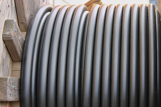
NEK606 Water Blocked
Offshore & Marine Cables
Water Blocked S10 IYOI(c) 60 V
Applications
-
These S10 IYOI(c) 60 V NEK606 Water Blocked Offshore & Marine cables are flame retardant, low smoke and halogen free, used for indoor telecommunication.
Standards
-
IEC 60092-359 IEC 60332-1 IEC 60332-3-22 IEC 60754-1,2 IEC 61034-1,2 NEK 606:2004 VG 95218 part 29
 60 V NEK606 Marine Cables")
Construction
-
l Conductors: Solid tinned copper, 0.5mm.
l Insulation: Halogen-free thermoplastic compound PE.
l Twinning: Colour coded cores twisted together. Pairs are cross-stranded to finished cable or 10 pair units. The units are stranded to 20 - 30 - 50 pair cables. 2 pair is stranded as a star quad.
l Filler: Water blocking fillers, if required.
l Wrapping: Polyester tape.
l Collective Shielding: The cable core is screened by copper backed polyester tape in contact with a 0.5mm solid tinned drain wire.
l Bedding: Halogen-free thermoplastic compound, type SHF1, coloured grey, PETP wrapping tape will be applied over the bedding, if required.
l Armour: Copper wire braid, PETP wrapping tape will be applied over the braiding, if required.
l Water Blocking Elements: Water blocking tape and strings for providing longitudinal water tightness.
l Inner Sheath: Halogen-free thermoplastic compound, type SHF1, coloured grey.
l Outer Sheath: Polyurethane for providing transversal water tightness, PE is optional,but can not meet low smoke standard.
Electrical Characteristics
| Nominal Conductor Diameter | mm | 0.5 |
|---|---|---|
| Maximum Resistant@20˚C | O/km | 95 |
| Nominal Inductance@1KHz | MH/km | 0.61 |
| Mutual Capacitance 1-pair cable | nF/km | 90 |
| Mutual Capacitance 2-pair cable | nF/km | 80 |
| Mutual Capacitance 4-pair and above cable | nF/km | 70 |
| Operating Voltage | V | 60 |
Mechanical and Thermal Properties
-
Bending Radius : 8×OD (during installation); 6×OD (fixed installed).
-
Temperature Range : -10˚C ~ +60˚C.
Dimensions and Weight
| Construction No. of elements×No. of cores in element×Core diameter(mm) | Nominal Insulation Thickness mm | Nominal Bedding Thickness mm | Nominal Inner Sheath Thickness mm | Nominal Outer Sheath Thickness mm | Nominal Overall Diameter mm |
|---|---|---|---|---|---|
| 1×2×0.5 | 0.2 | 1.2 | 1.2 | 1 | 10.0±2.0 |
| 2×2×0.5 | 0.2 | 1.2 | 1.2 | 1 | 11.0±2.0 |
| 4×2×0.5 | 0.2 | 1.2 | 1.2 | 1 | 12.0±2.0 |
| 10×2×0.5 | 0.2 | 1.5 | 1.5 | 1 | 14.0±2.0 |
| 20×2×0.5 | 0.2 | 1.5 | 1.5 | 1 | 17.0±2.0 |