PRODUCTS
- Aerial Bundled Cables
- Airport Cables
- Automotive Cables
- Alarm & Audio & Electronic Cables
- Belden Equivalent Cables
- Bus Cables
- Cable Glands
- Cables for Oil Industry
- Coaxial Cables
- Composite Cables
- Control Cables
- Data Cable
- Elevator Cables
- Fiber Optic Cables
- Fire Resisting Cable(Fireflix)
- Fire Retardant Cable(FIRETOX)
- Flame Retardant Cable (FIREGUARD)
- Flexible Cables
- Heat Detection Cables
- High Temperature Cables
- Highway Cables
- Industrial Cables
- Instrumentation Cables
- Lan Cables
- Marine Cable
- NEK606 Water Blocked Offshore & Marine Cables
- IEC60092 STANDARD Offshore & Marine Cables
- BS 6883&BS7917 STANDARD Offshore & Marine Cables
- UKOOA Offshore & Marine cables
- VG 95218 Navy Cables
- Mining Cables
- Airframe Wire
- Marine, OIL,GAS & Petrochemical Cables
- Power Cables
- Railway Cables
- Robotics
- Rolling Stock Cables
- Rubber & Crane Cables
- Security Cables
- Special Cables
- Spiral Cables
- Telephone Cables
- Thermocouple Cables
- BS 5308 Cable
- PAS 5308 Cable
- BS 5467 Cable
- BS 6724 Cable
- BS 6346 Cable
- BS 7211 Cable
- IEC 60502-1 Cable
HOT PRODUCTS
APPLICATIONS
|
NEK606 Water Blocked
Offshore & Marine Cables
Water Blocked P5 or P5/P12 BFOU 0.6/1KV
Applications
-
These P5 or P5/P12 BFOU 0.6/1KV NEK606 Water Blocked Offshore & Marine cables are fire resistant, flame retardant, low smoke,halogen free and mud resistant, used for control, power and lighting systems.
Standards
-
IEC 60092-353 IEC 60092-351 IEC 60092-359 IEC 60332-1 IEC 60332-3-22 IEC 60754-1,2 IEC 61034-1,2 NEK 606:2004 VG 95218 part 29

Construction
-
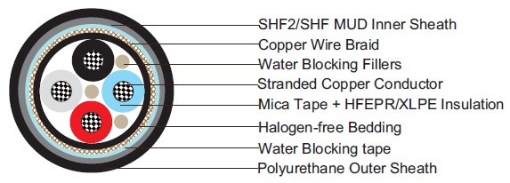
l Conductors: Tinned annealed stranded compacted copper to IEC 60228 class 2.
l Insulation: Mica tape + Halogen free EPR/Mica tape + XLPE.
l Filler: Water blocking fillers, if required.
l Bedding: Halogen free compound, PETP wrapping tape will be applied over the bedding, if required.
l Armour: Tinned copper wire braid, PETP wrapping tape will be applied over the braiding, if required.
l Water Blocking Elements: Water blocking tape and strings for providing longitudinal water tightness.
l Inner Sheath: Halogen free thermosetting compound, SHF2 (for TYPE P5). Halogen free, mud resistant thermosetting compound, SHF MUD (for TYPE P5/P12), coloured black.
l Outer Sheath: Polyurethane for providing transversal water tightness, PE is optional,but can not meet low smoke standard.
Electrical Characteristics
-
Nominal Cross Section Area mm2 1.5 2.5 4 6 10 16 25 35 50 Nominal Conductor Diameter mm 1.6 2.1 2.6 3.2 4 5.1 6.5 7.4 8.7 Maximum DC Resistant@20˚C O/km 12.2 7.56 4.7 3.11 1.84 1.16 0.734 0.529 0.391 Continuous Current Rating@45˚C1 Core A 23 30 40 52 72 96 127 157 196 Continuous Current Rating@45˚C2 Core A 20 26 34 44 61 82 108 133 167 Continuous Current Rating@45˚C3&4 Core A 16 21 28 36 50 67 89 110 137 Short Circuit Current 1s A 210 360 570 860 1430 2290 3580 5010 7150 Operating Voltage KV 0.6/1 0.6/1 0.6/1 0.6/1 0.6/1 0.6/1 0.6/1 0.6/1 0.6/1 Nominal Cross Section Area mm2 70 95 120 150 185 240 300 400 630 Nominal Conductor Diameter mm 10.3 12.2 13.8 15.1 17.0 19.6 21.9 24.6 32.5 Maximum DC Resistant@20˚C O/km 0.27 0.195 0.154 0.126 0.1 0.0762 0.0607 0.0475 0.0286 Continuous Current Rating@45˚C1 Core A 242 293 339 389 444 522 601 690 890 Continuous Current Rating@45˚C2 Core A 206 249 288 331 444 444 511 587 757 Continuous Current Rating@45˚C3&4 Core A 169 205 237 272 311 365 421 483 623 Short Circuit Current 1s A 10020 13590 17170 21460 26470 34340 42930 57230 90140 Operating Voltage KV 0.6/1 0.6/1 0.6/1 0.6/1 0.6/1 0.6/1 0.6/1 0.6/1 0.6/1
-
Note: For more than 4-cores, the current ratings may be calculated from the following formula (IN=I1/ 3v N ), I1= Current rating for 1-core, N = Number of cores.
Ambient Temperature Correction Factors
-
Ambient Temperature Correction Factors 35 40 45 50 55 60 65 70 75 80 Rating Factor 1.1 1.05 1.0 0.94 0.88 0.82 0.74 0.67 0.58 0.47
Mechanical and Thermal Properties
-
Bending Radius : 8×OD (during installation); 6×OD (fixed installed).
-
Temperature Range : -20˚C ~ +90˚C.
Dimensions and Weight
| Construction No. of cores×Cross section (mm2) | Nominal Insulation Thickness mm | Nominal Bedding Thickness mm | Nominal Inner Sheath Thickness mm | Nominal Outer Sheath Thickness mm | ||
|---|---|---|---|---|---|---|
| Nominal Overall Diameter mm | Nominal Weight kg/km | |||||
| 1×1.5 | 1 | 1.1 | 1.1 | 1 | 11.3±2 | 152 |
| 1×2.5 | 1 | 1.1 | 1.1 | 1 | 11.7±2 | 168 |
| 1×4 | 1 | 1.1 | 1.1 | 1 | 12.4±2 | 231 |
| 1×6 | 1 | 1.1 | 1.1 | 1 | 12.9±2 | 263 |
| 1×10 | 1 | 1.1 | 1.2 | 1 | 14.7±2 | 326 |
| 1×16 | 1 | 1.1 | 1.2 | 1 | 15.9±2 | 410 |
| 1×25 | 1.2 | 1.1 | 1.3 | 1.2 | 18.7±2 | 614 |
| 1×35 | 1.2 | 1.1 | 1.3 | 1.2 | 19.6±2 | 725 |
| 1×50 | 1.4 | 1.1 | 1.4 | 1.2 | 21.4±2 | 935 |
| 1×70 | 1.4 | 1.1 | 1.4 | 1.2 | 23.0±2 | 1166 |
| 1×95 | 1.6 | 1.1 | 1.5 | 1.4 | 25.9±2 | 1512 |
| 1×120 | 1.6 | 1.2 | 1.6 | 1.4 | 27.8±2 | 1822 |
| 1×150 | 1.8 | 1.2 | 1.7 | 1.4 | 29.8±2 | 2163 |
| 1×185 | 2 | 1.2 | 1.7 | 1.4 | 32.2±2 | 2672 |
| 1×240 | 2.2 | 1.2 | 1.8 | 1.6 | 35.8±2 | 3329 |
| 1×300 | 2.4 | 1.2 | 1.9 | 1.6 | 38.5±2 | 4106 |
| 1×400 | 2.4 | 1.4 | 2.1 | 1.6 | 44.2±2 | 5355 |
| 1×630 | 2.8 | 1.4 | 2.3 | 1.6 | 51.7±2 | 8043 |
| 2×1.5 | 1 | 1.1 | 1.2 | 1 | 16.2±2 | 326 |
| 2×2.5 | 1 | 1.1 | 1.3 | 1 | 17.1±2 | 378 |
| 2×4 | 1 | 1.1 | 1.3 | 1 | 18.6±2 | 494 |
| 2×6 | 1 | 1.1 | 1.4 | 1 | 19.9±2 | 583 |
| 2×10 | 1 | 1.1 | 1.4 | 1 | 21.9±2 | 740 |
| 2×16 | 1 | 1.1 | 1.5 | 1 | 24.5±2 | 1034 |
| 2×25 | 1.2 | 1.2 | 1.6 | 1.2 | 28.8±2 | 1428 |
| 2×35 | 1.2 | 1.2 | 1.7 | 1.2 | 30.8±2 | 1701 |
| 2×50 | 1.4 | 1.2 | 1.9 | 1.2 | 34.8±2 | 2405 |
| 2×70 | 1.4 | 1.2 | 2.1 | 1.2 | 40.4±2 | 3423 |
| 2×95 | 1.6 | 1.2 | 2.3 | 1.4 | 44.4±2 | 4106 |
| 2×120 | 1.6 | 1.4 | 2.4 | 1.4 | 48.1±2 | 4946 |
| 2×150 | 1.8 | 1.4 | 2.6 | 1.4 | 52.5±2 | 5954 |
| 2×185 | 2 | 1.4 | 2.7 | 1.4 | 57.1±2 | 7182 |
| 2×240 | 2.2 | 1.6 | 3 | 1.6 | 64.7±2 | 9230 |
| 2×300 | 2.4 | 1.6 | 3.2 | 1.6 | 71.0±2 | 11162 |
| 3×1.5 | 1 | 1.1 | 1.3 | 1 | 16.8±2 | 362 |
| 3×2.5 | 1 | 1.1 | 1.3 | 1 | 18.2±2 | 467 |
| 3×4 | 1 | 1.1 | 1.3 | 1 | 19.4±2 | 557 |
| 3×6 | 1 | 1.1 | 1.4 | 1 | 20.7±2 | 667 |
| 3×10 | 1 | 1.1 | 1.5 | 1 | 23.1±2 | 872 |
| 3×16 | 1 | 1.1 | 1.5 | 1 | 25.7±2 | 1218 |
| 3×25 | 1.2 | 1.2 | 1.7 | 1.2 | 30.5±2 | 1722 |
| 3×35 | 1.2 | 1.2 | 1.8 | 1.2 | 32.6±2 | 2079 |
| 3×50 | 1.4 | 1.2 | 2 | 1.2 | 36.7±2 | 2888 |
| 3×70 | 1.4 | 1.2 | 2.2 | 1.2 | 41.4±2 | 3859 |
| 3×95 | 1.6 | 1.4 | 2.4 | 1.4 | 47.5±2 | 5203 |
| 3×120 | 1.6 | 1.4 | 2.5 | 1.4 | 51.1±2 | 6337 |
| 3×150 | 1.8 | 1.4 | 2.7 | 1.4 | 56.0±2 | 7723 |
| 3×185 | 2 | 1.6 | 2.9 | 1.4 | 62.3±2 | 9476 |
| 3×240 | 2.2 | 1.6 | 3.2 | 1.6 | 69.7±2 | 12170 |
| 3×300 | 2.4 | 1.8 | 3.4 | 1.6 | 75.8±2 | 14427 |
| 4×1.5 | 1 | 1.1 | 1.3 | 1 | 18.4±2 | 420 |
| 4×2.5 | 1 | 1.1 | 1.3 | 1 | 19.3±2 | 530 |
| 4×4 | 1 | 1.1 | 1.4 | 1 | 20.8±2 | 651 |
| 4×6 | 1 | 1.1 | 1.4 | 1 | 22.1±2 | 788 |
| 4×10 | 1 | 1.1 | 1.5 | 1 | 24.7±2 | 1034 |
| 4×16 | 1 | 1.2 | 1.6 | 1 | 27.9±2 | 1470 |
| 4×25 | 1.2 | 1.2 | 1.8 | 1.2 | 33.1±2 | 2095 |
| 4×35 | 1.2 | 1.2 | 1.9 | 1.2 | 35.5±2 | 2562 |
| 4×50 | 1.4 | 1.4 | 2 | 1.2 | 40.6±2 | 3602 |
| 4×70 | 1.4 | 1.4 | 2.2 | 1.2 | 45.1±2 | 4830 |
| 4×95 | 1.6 | 1.6 | 2.4 | 1.4 | 52.2±2 | 6442 |
| 4×120 | 1.6 | 1.6 | 2.5 | 1.4 | 56.4±2 | 7891 |
| 4×150 | 1.8 | 1.6 | 2.9 | 1.4 | 61.8±2 | 9461 |
| 4×185 | 2 | 1.6 | 3.1 | 1.4 | 67.5±2 | 11550 |
| 4×240 | 2.2 | 1.8 | 3.4 | 1.6 | 76.3±2 | 14868 |
| 4×300 | 2.4 | 1.8 | 3.7 | 1.6 | 83.9±2 | 18428 |
| 5×1.5 | 1 | 1.1 | 1.4 | 1 | 19.7±2 | 536 |
| 6×1.5 | 1 | 1.1 | 1.4 | 1 | 21.0±2 | 572 |
| 7×1.5 | 1 | 1.1 | 1.4 | 1 | 21.0±2 | 620 |
| 8×1.5 | 1 | 1.1 | 1.5 | 1 | 23.8±2 | 751 |
| 9×1.5 | 1 | 1.1 | 1.6 | 1 | 25.3±2 | 756 |
| 10×1.5 | 1 | 1.1 | 1.6 | 1 | 25.6±2 | 830 |
| 12×1.5 | 1 | 1.2 | 1.6 | 1 | 26.3±2 | 924 |
| 14×1.5 | 1 | 1.2 | 1.7 | 1 | 27.5±2 | 1013 |
| 16×1.5 | 1 | 1.2 | 1.7 | 1 | 28.7±2 | 1087 |
| 19×1.5 | 1 | 1.2 | 1.7 | 1 | 29.4±2 | 1244 |
| 20×1.5 | 1 | 1.2 | 1.8 | 1 | 31.5±2 | 1323 |
| 23×1.5 | 1 | 1.2 | 1.9 | 1 | 33.8±2 | 1507 |
| 24×1.5 | 1 | 1.2 | 2 | 1 | 35.2±2 | 1586 |
| 27×1.5 | 1 | 1.2 | 2 | 1 | 35.9±2 | 1696 |
| 30×1.5 | 1 | 1.2 | 2 | 1 | 36.9±2 | 1822 |
| 32×1.5 | 1 | 1.4 | 2 | 1 | 37.5±2 | 1890 |
| 33×1.5 | 1 | 1.4 | 2 | 1 | 38.7±2 | 2037 |
| 37×1.5 | 1 | 1.4 | 2 | 1 | 40.0±2 | 2195 |
| 44×1.5 | 1 | 1.4 | 2.3 | 1 | 44.6±2 | 2583 |
| 5×2.5 | 1 | 1.1 | 1.4 | 1 | 20.8±2 | 625 |
| 6×2.5 | 1 | 1.1 | 1.4 | 1 | 22.4±2 | 683 |
| 7×2.5 | 1 | 1.1 | 1.4 | 1 | 22.4±2 | 735 |
| 8×2.5 | 1 | 1.1 | 1.5 | 1 | 25.5±2 | 830 |
| 9×2.5 | 1 | 1.1 | 1.6 | 1 | 27.1±2 | 903 |
| 10×2.5 | 1 | 1.1 | 1.6 | 1 | 27.4±2 | 1003 |
| 12×2.5 | 1 | 1.2 | 1.6 | 1 | 28.1±2 | 1097 |
| 14×2.5 | 1 | 1.2 | 1.7 | 1 | 29.3±2 | 1218 |
| 16×2.5 | 1 | 1.2 | 1.8 | 1 | 30.8±2 | 1328 |
| 19×2.5 | 1 | 1.2 | 1.8 | 1 | 31.6±2 | 1517 |
| 20×2.5 | 1 | 1.2 | 1.9 | 1 | 33.8±2 | 1622 |
| 23×2.5 | 1 | 1.4 | 2 | 1 | 36.7±2 | 1895 |
| 24×2.5 | 1 | 1.4 | 2 | 1 | 37.8±2 | 1943 |
| 27×2.5 | 1 | 1.4 | 2 | 1 | 37.4±2 | 2069 |
| 30×2.5 | 1 | 1.4 | 2.1 | 1 | 40.1±2 | 2347 |
| 33×2.5 | 1 | 1.4 | 2.2 | 1 | 41.6±2 | 2510 |
| 37×2.5 | 1 | 1.4 | 2.3 | 1 | 43.2±2 | 2741 |
| 44×2.5 | 1 | 1.4 | 2.4 | 1 | 48.2±2 | 3229 |


