

PRODUCTS
- Aerial Bundled Cables
- Airport Cables
- Automotive Cables
- Alarm & Audio & Electronic Cables
- Belden Equivalent Cables
- Bus Cables
- Cable Glands
- Cables for Oil Industry
- Coaxial Cables
- Composite Cables
- Control Cables
- Data Cable
- Elevator Cables
- Fiber Optic Cables
- Fire Resisting Cable(Fireflix)
- Fire Retardant Cable(FIRETOX)
- Flame Retardant Cable (FIREGUARD)
- Flexible Cables
- Heat Detection Cables
- High Temperature Cables
- Highway Cables
- Industrial Cables
- Instrumentation Cables
- Lan Cables
- Marine Cable
- NEK606 Water Blocked Offshore & Marine Cables
- IEC60092 STANDARD Offshore & Marine Cables
- BS 6883&BS7917 STANDARD Offshore & Marine Cables
- UKOOA Offshore & Marine cables
- VG 95218 Navy Cables
- Mining Cables
- Airframe Wire
- Marine, OIL,GAS & Petrochemical Cables
- Power Cables
- Railway Cables
- Robotics
- Rolling Stock Cables
- Rubber & Crane Cables
- Security Cables
- Special Cables
- Spiral Cables
- Telephone Cables
- Thermocouple Cables
- BS 5308 Cable
- PAS 5308 Cable
- BS 5467 Cable
- BS 6724 Cable
- BS 6346 Cable
- BS 7211 Cable
- IEC 60502-1 Cable
HOT PRODUCTS
APPLICATIONS
|
NEK606 Water Blocked
Offshore & Marine Cables
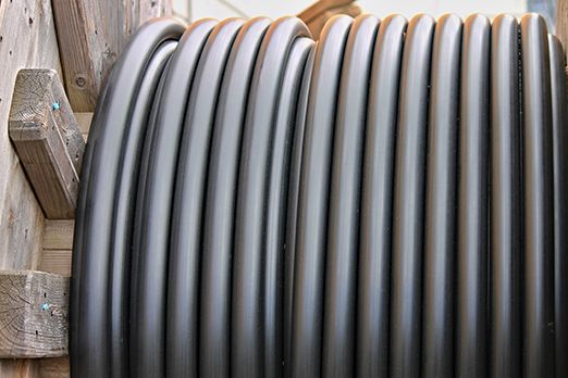
Water Blocked S15 BFOU-HCF(i) 250 V
Applications
-
These S15 BFOU-HCF(i) 250 V NEK606 Water Blocked Offshore Marine Cables are fire resistant, flame retardant, low smoke and halogen free, used for emergency instrumentation, communication, control and alarm systems that need to be operational during a 1100˚C hydrocarbon fire.
Standards
-
IEC 60092-376 IEC 60092-351 IEC 60092-359 IEC 60332-1 IEC 60332-3-22 IEC 60754-1,2 IEC 61034-1,2 NEK 606:2004 IEC 60331-21 VG 95218 part 29?
 250 V NEK606 Marine cables")
Construction
-
l Conductors: Circular tinned annealed stranded copper wire to IEC 60228 class 2.
l Insulation: Mica tape + Halogen free EPR compound.
l Twinning: Colour coded cores twisted together.
l Individual Shielding: Each pairs/triples are screened by copper backed polyester tape in contact with a stranded tinned copper drain wire and wrapped with polyester tape. Pairs/triples are numbered with numbered tape or by numbers printed directly on the insulated conductors.
l Filler: Water blocking fillers, if required.
l Bedding: Halogen free compound, PETP wrapping tape will be applied over the bedding, if required.
l Armour: Tinned copper wire braid, PETP wrapping tape will be applied over the braiding, if required.
l Water Blocking Elements: Water blocking tape and strings for providing longitudinal water tightness.l Inner Sheath: Halogen free thermosetting compound, SHF2.
l HC-fire protection: Extruded thermoplastic fire protection compound.l Taping: Lapped glass fibre tape.
l Outer Sheath 1: Flame retardant halogen-free thermoplastic compound, type SHF1, coloured grey (blue for intrinsically safe).
l Outer Sheath 2: Polyurethane for providing transversal water tightness, PE is optional,but can not meet low smoke standard.
Electrical Characteristics
-
Nominal Cross Section Area mm2 1.5 Nominal Conductor Diameter mm 1.6 Maximum Resistant@20˚C O/km 12.9 Mutual Capacitance nF/km 100 Nominal Inductance@1KHz MH/km 0.673 Operating Voltage V 250
Mechanical and Thermal Properties
-
Bending Radius : 20×OD (during installation); 12×OD (fixed installed).
-
Temperature Range : -20˚C ~ +90˚C.
Dimensions and Weight
| Construction No. of elements×No. of cores in element×Cross section (mm2) |
Nominal Insulation Thickness mm |
Nominal Diameter Over Bedding mm |
Nominal Diameter Over Inner Sheath mm |
Nominal Overall Diameter mm |
Nominal Weight kg/km |
|---|---|---|---|---|---|
| 1×2×1.5 | 0.7 | 9.0 | 13.1 | 41.5±2 | 1974 |
| 2×2×1.5 | 0.7 | 13.0 | 16.8 | 46.5±2 | 2573 |
| 4×2×1.5 | 0.7 | 15.0 | 20.7 | 49.5±2 | 2972 |
| 8×2×1.5 | 0.7 | 21.0 | 26.4 | 56.0±2 | 3875 |
| 12×2×1.5 | 0.7 | 25.0 | 31.2 | 65.0±2 | 5460 |