Multipair Instrument Cables ESI 09-6 Issue 5
Applications
These light current control cables are intended primarily for use with control, indication and alarm equipment for switchgear and similar power apparatus in power stations and substations where the nominal voltage does not exceed 150V d.c. or 110V a.c.The cables are also suitable for telemetry applications where large conductor size are required. An optional collective aluminum tape screen can be provided. In case if the installation environment is prone to flooding or prolonged period of dampness, PE insulation should be considered as an alternative to PVC.
Construction
| Conductor |
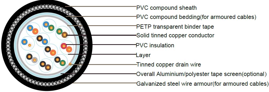
Solid tinned annealed copper, sizes: 1/0.9mm(0.64mm2) to BS6360 |
| Insulation |
PVC (polyvinyl chloride) type 2 to BS7655 |
| Pairing |
Two insulated conductors uniformly twisted together with a lay not exceeding 100mm |
| Colour code |
See technical information |
| Binder tape |
PETP transparent tape |
| Collective screen(optional) |
Aluminum/polyester tape is applied over the laid up pairs metallic side down in contact with a longitudinal 1/0.5mm to 1/0.8mm tinned copper drain wire |
| Bedding (for armoured cables) |
PVC (polyvinyl chloride) to type TM 1 or 6 to BS EN 50363-4-1 |
| Armouring (for armoured cables) |
Galvanized steel wire armour |
| Outer sheath |
Black PVC (polyvinyl chloride) to type TM 1 or 6 to BS EN 50363-4-1 |
Electrical Properties
| Maximum conductor temperature |
+70?C |
| Minimum bending radius |
6 x overall diamter |
| Minimum ambient temperature |
- 20C after installation and only when cable is in a fixed position |
| Voltage rating |
150V d.c. or 110V a.c. |
| Test voltage |
2Kv r.m.s. between conductors, 5Kv r.m.s. between all conductors and aromur |
| Maximum conductor resistance(loop) |
59.34Ohm/km at 20 ?C |
| Minimum insulation resistance |
80MOhm/km at 20 ?C |
| Maximum mutual capacitance |
150Nf/km at 1 KHz |
| Flame retardancy |
BS 4066 part 1(IEC 60332-1) or BS 4066 part 3(IEC 60332-3) |
Parameter
Unarmoured
| Number of pairs |
Nominal diameter of conductor |
Nominal Conductor Cross-Sectional Area |
Insulation thickness |
Sheath thickness |
Diameter Under Armour |
Cable weight |
| no./mm |
mm² |
mm |
mm |
mm |
Kg/Km |
| UN-SCREENED CABLES |
| 2(Q) |
0.9 |
0.64 |
0.3 |
1.3 |
5.7 |
45 |
| 5 |
0.9 |
0.64 |
0.3 |
1.4 |
9.4 |
115 |
| 10 |
0.9 |
0.64 |
0.3 |
1.5 |
13 |
205 |
| 20 |
0.9 |
0.64 |
0.3 |
1.6 |
16.8 |
380 |
| 30 |
0.9 |
0.64 |
0.3 |
1.7 |
19.9 |
570 |
| 50 |
0.9 |
0.64 |
0.3 |
1.9 |
25.4 |
920 |
| 100 |
0.9 |
0.64 |
0.3 |
2 |
35.5 |
1820 |
| SCREENED CABLES |
| 2(Q) |
0.9 |
0.64 |
0.3 |
1.3 |
6.2 |
50 |
| 5 |
0.9 |
0.64 |
0.3 |
1.4 |
9.9 |
125 |
| 10 |
0.9 |
0.64 |
0.3 |
1.5 |
13.5 |
215 |
| 20 |
0.9 |
0.64 |
0.3 |
1.6 |
17.3 |
390 |
| 30 |
0.9 |
0.64 |
0.3 |
1.7 |
20.4 |
580 |
| 50 |
0.9 |
0.64 |
0.3 |
1.9 |
25.9 |
940 |
| 100 |
0.9 |
0.64 |
0.3 |
2 |
36 |
1850 |
armoured
| Number of pairs |
Nominal diameter of conductor |
Insulation thickness |
Bedding Thickness |
Diameter Under Armour |
Diameter of armour wire |
Sheath thickness |
Overall diameter |
Cable weight |
| mm |
mm |
mm |
mm |
mm |
mm |
mm |
Kg/Km |
| UN-SCREENED CABLES |
| 2(Q) |
0.9 |
0.3 |
0.8 |
5.7 |
0.9 |
1.3 |
10.1 |
200 |
| 5 |
0.9 |
0.3 |
1 |
9.4 |
0.9 |
1.4 |
14.1 |
370 |
| 10 |
0.9 |
0.3 |
1.1 |
13 |
1.25 |
1.5 |
18.6 |
610 |
| 20 |
0.9 |
0.3 |
1.2 |
16.8 |
1.25 |
1.6 |
22.7 |
930 |
| 30 |
0.9 |
0.3 |
1.4 |
19.9 |
1.6 |
1.7 |
26.7 |
1390 |
| 50 |
0.9 |
0.3 |
1.6 |
25.4 |
1.6 |
1.9 |
32.6 |
1940 |
| 100 |
0.9 |
0.3 |
1.9 |
35.5 |
2 |
2 |
44.1 |
3700 |
| SCREENED CABLES |
| 2(Q) |
0.9 |
0.3 |
0.8 |
6.2 |
0.9 |
1.3 |
10.6 |
220 |
| 5 |
0.9 |
0.3 |
1 |
9.9 |
0.9 |
1.4 |
14.6 |
380 |
| 10 |
0.9 |
0.3 |
1.1 |
13.5 |
1.25 |
1.5 |
19.1 |
630 |
| 20 |
0.9 |
0.3 |
1.2 |
17.3 |
1.25 |
1.6 |
23.2 |
955 |
| 30 |
0.9 |
0.3 |
1.4 |
20.4 |
1.6 |
1.7 |
27.2 |
1415 |
| 50 |
0.9 |
0.3 |
1.6 |
25.9 |
1.6 |
1.9 |
33.1 |
2000 |
| 100 |
0.9 |
0.3 |
1.9 |
36 |
2 |
2 |
44.6 |
3750 |


