

PRODUCTS
- Aerial Bundled Cables
- Airport Cables
- Automotive Cables
- Alarm & Audio & Electronic Cables
- Belden Equivalent Cables
- Bus Cables
- Cable Glands
- Cables for Oil Industry
- Coaxial Cables
- Composite Cables
- Control Cables
- Data Cable
- Elevator Cables
- Fiber Optic Cables
- Fire Resisting Cable(Fireflix)
- Fire Retardant Cable(FIRETOX)
- Flame Retardant Cable (FIREGUARD)
- Flexible Cables
- Heat Detection Cables
- High Temperature Cables
- Highway Cables
- Industrial Cables
- Instrumentation Cables
- Lan Cables
- Marine Cable
- NEK606 Water Blocked Offshore & Marine Cables
- IEC60092 STANDARD Offshore & Marine Cables
- BS 6883&BS7917 STANDARD Offshore & Marine Cables
- UKOOA Offshore & Marine cables
- VG 95218 Navy Cables
- Mining Cables
- Airframe Wire
- Marine, OIL,GAS & Petrochemical Cables
- Power Cables
- Railway Cables
- Robotics
- Rolling Stock Cables
- Rubber & Crane Cables
- Security Cables
- Special Cables
- Spiral Cables
- Telephone Cables
- Thermocouple Cables
- BS 5308 Cable
- PAS 5308 Cable
- BS 5467 Cable
- BS 6724 Cable
- BS 6346 Cable
- BS 7211 Cable
- IEC 60502-1 Cable
HOT PRODUCTS

APPLICATIONS
|
450/750V XLPE Insulated, LSZH Sheathed, Screened Power Cables (2-4cores)
FTX200 07RCZ1-R (CU/XLPE/CUTO/LSZH 450/750V Class 2)
APPLICATION
The Firetox Flame Retardant Cables are mainly used in power stations, mass transit underground passenger systems, airports, petrochemical plants, hotels, hospitals, and high-rise buildings.STANDARDS
Basic design to BS 7211; IEC 60502-1FIRE PERFORMANCE
| Flame Retardance (Single Vertical Wire Test) | EN 60332-1-2; IEC 60332-1-2; BS EN 60332-1-2; VDE 0482-332-1 ; NBN C 30-004 (cat. F1); NF C32-070-2.1(C2); CEI 20-35/1-2; EN 50265-2-1*; DIN VDE 0482-265-2-1* |
| Reduced Fire Propagation (Vertically-mounted bundled wires & cable test) | EN 60332-3-24 (cat. C); IEC 60332-3-24; BS EN 60332-3-24; VDE 0482-332-3; NBN C 30-004 (cat. F2); NF C32-070-2.2(C1); CEI 20-22/3-4; EN 50266-2-4*; DIN VDE 0482-266-2-4 |
| Halogen Free | IEC 60754-1; EN 50267-2-1; DIN VDE 0482-267-2-1; CEI 20-37/2-1 ; BS 6425-1* |
| No Corrosive Gas Emission | IEC 60754-2; EN 50267-2-2; DIN VDE 0482-267-2-2; CEI 20-37/2-2 ; BS 6425-2* |
| minimum Smoke Emission | IEC 61034-1&2; EN 61034 -1&2; DIN VDE 0482-1034-1&2; CEI 20-37/3-1&2; EN 50268-1&2*; BS 7622-1&2* |
| No Toxic gases | NES 02-713; NF C 20-454 |
Note: Asterisk * denotes superseded standard.
VOLTAGE RATING
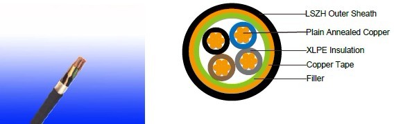
450/750VCABLE CONSTRUCTION
Conductor: Plain annealed copper wire, stranded according to IEC(EN) 60228 class 2.Insulation: Extruded cross-linked XLPE compound.
Filler, binder (if any): PP, PET, LSZH
Overall Screen: Copper tape
Outer Sheath: Thermoplastic LSZH compound type LTS3 as per BS 7655-6.1 (Thermosetting LSZH
compound type SW2-SW4 as per BS 7655-2.6 can be offered.)
COLOUR CODE
Insulation colour as per bs7671| with earth conductor | without earth conductor | |
| 2Cores | - | Brown,Blue |
| 3Cores | Yellow/Green,Brown,Blue | Brown,Gray,Black |
| 4Cores | Yellow/Green,Brown,Gray,Black | Brown,Gray,Black,Blue |
| 5Cores | Yellow/Green,Brown,Gray,Black,Blue | Brown,Gray,Black,Blue,Black |
above 5 Cores |
Yellow/Green,Black Numbered |
Black Numbered |
sheath colour: Black
Physical AND THERMAL PROPERTIES
Temperature range during operation: Max.90°C for XLPE250°C in short-circuit for 5s max.
Minimum bending radius: 6 x Overall Diameter
CONSTRUCTION PARAMETERS
Conductor |
FTx200 07RcZ1-R |
|||||||
|---|---|---|---|---|---|---|---|---|
| No. of Core X Cross Section | No./ Nominal Diameter of Strands | Nominal Overall Diameter Conductor | Nominal Insulation Thickness | Nominal Copper Tape Thickness | Nominal Sheath Thickness | Nominal Overall Diameter | max.DC resistance of conductor @20°C | Approx. Weight |
| Noxmm2 | No./mm | mm | mm | mm | mm | mm | Ω/km | kg/km |
| 2x1.0 | 7/0.44 | 1.32 | 0.7 | 0.1 | 1.2 | 10.7 | 18.1 | 172 |
| 2x1.5 | 7/0.53 | 1.59 | 0.7 | 0.1 | 1.3 | 11.3 | 12.1 | 197 |
| 2x2.5 | 7/0.67 | 2.01 | 0.7 | 0.1 | 1.3 | 12.2 | 7.41 | 239 |
| 2x4.0 | 7/0.85 | 2.55 | 0.7 | 0.1 | 1.3 | 13.4 | 4.61 | 300 |
| 3x1.0 | 7/0.44 | 1.32 | 0.7 | 0.1 | 1.3 | 11.2 | 18.1 | 194 |
| 3x1.5 | 7/O.53 | 1.59 | 0.7 | 0.1 | 1.3 | 11.8 | 12.1 | 224 |
| 3x2.5 | 7/0,67 | 2.01 | 0.7 | 0.1 | 1.3 | 12.8 | 7.41 | 276 |
| 3x4.0 | 7/0.85 | 2.55 | 0.7 | 0.1 | 1.3 | 14.1 | 4.61 | 353 |
| 4x1.0 | 7/0.44 | 1.32 | 0.7 | 0.1 | 1.3 | 12.0 | 18.1 | 224 |
| 4x1.5 | 7/0.53 | 1.59 | 0.7 | 0.1 | 1.4 | 12.7 | 12.1 | 261 |
| 4x2.5 | 7/0.67 | 2.01 | 0.7 | 0.1 | 1.3 | 13.9 | 7.41 | 326 |
| 4x4.0 | 7/0.85 | 2.55 | 0.7 | 0.1 | 1.3 | 15.3 | 4.61 | 422 |
Electrical PROPERTIES
Conductor Operating Temperature : 90°CAmbient Temperature : 30°C
Current-Carrying Capacities (Amp)
| Conductor cross- sectional area | Reference method 4 (enclosed in conduit in thermally insulating wall etc) | Reference method 3 (enclosed in conduit on a wall or in trunking etc) | Reference method 1 (clipped direct) | Reference method 11 (on a perforated cable tray, horizontal or vertical) | Reference method 12 (free air) | ||||||
|---|---|---|---|---|---|---|---|---|---|---|---|
| Horizontal flat spaced | Vertical flat spaced | Trefoil | |||||||||
| 2 cables, single- phase a.c. or d.c. | 3 or 4 cables, 3-phase a.c. | 2 cables, single- phase a.c. or d.c | 3 or 4 cables, 3-phase a.c. | 2 cables, single- phase a.c. or d.c. flat and touching | 3 or 4 cables, 3-phase a.c. flat and touching or trefoil | 2 cables, single- phase a.c. or d.c. or flat and touching | 3 or 4 cables, 3-phase a.c. flat and touching or trefoil | 2 cables, single- phase a.c. or d.c. or 3 c ables three phase | 2 cables, single- phase a.c. or d.c. or 3 cables three phase | 3 cables, trefoil 3-phase a.c. | |
| 1 | 2 | 3 | 4 | 5 | 6 | 7 | 8 | 9 | 10 | 11 | 12 |
| mm2 | A | A | A | A | A | A | A | A | A | A | A |
| 1.0 | 13 | - | - | - | 15 | - | - | - | - | - | - |
| 1.5 | 18 | 17 | 22 | 19 | 25 | 23 | - | - | - | - | - |
| 2.5 | 24 | 23 | 30 | 26 | 34 | 31 | - | - | - | - | - |
| 4 | 33 | 30 | 40 | 35 | 46 | 41 | - | - | - | - | - |
Voltage Drop (Per Amp Per Meter)
| Nominal Cross Section Area | 2 cables d.c. | 2 cables, single-phase a.c. | 3 or 4 cables, 3-phase a.c. | |||||||||
|---|---|---|---|---|---|---|---|---|---|---|---|---|
| Ref. Methods 3 and 4 (enclosed in conduit etc, in or on a wall) | Ref. Methods 1 and 11 (clipped direct or on trays touching) | Ref. Methods 3 and 4 (enclosed in conduit etc, in or on a wall) | Ref. Methods 1, 11 and 12 (in trefoil) | Ref. Methods 1 and 11(Flat and touching) | ||||||||
| 1 | 2 | 3 | 4 | 5 | 6 | 7 | ||||||
| mm2 | mV/A/m | mV/A/m | mV/A/m | mV/A/m | mV/A/m | mV/A/m | ||||||
| 1.0 | 46 | 46 | - | - | - | - | ||||||
| 1.5 | 31 | 31 | 27 | 27 | 27 | 27 | ||||||
| 2.5 | 19 | 19 | 16 | 16 | 16 | 16 | ||||||
| 4 | 33 | 12 | 10 | 10 | 10 | 10 | ||||||
© 2022 Caledonian cables