

PRODUCTS
- Aerial Bundled Cables
- Airport Cables
- Automotive Cables
- Alarm & Audio & Electronic Cables
- Belden Equivalent Cables
- Bus Cables
- Cable Glands
- Cables for Oil Industry
- Coaxial Cables
- Composite Cables
- Control Cables
- Data Cables
- Elevator Cables
- Fiber Optic Cables
- Fire Resisting Cable(Fireflix)
- Fire Retardant Cable(FIRETOX)
- Flame Retardant Cable (FIREGUARD)
- Flexible Cables
- Heat Detection Cables
- High Temperature Cables
- Highway Cables
- Industrial Cables
- Instrumentation Cables
- Marine Cable
- NEK606 Water Blocked Offshore & Marine Cables
- IEC60092 STANDARD Offshore & Marine Cables
- BS 6883&BS7917 STANDARD Offshore & Marine Cables
- UKOOA Offshore & Marine cables
- VG 95218 Navy Cables
- Mining Cables
- Airframe Wire
- Marine, OIL,GAS & Petrochemical Cables
- Power Cables
- Railway Cables
- Robotics
- Rolling Stock Cables
- Rubber & Crane Cables
- Security Cables
- Special Cables
- Spiral Cables
- Telephone Cables
- Thermocouple Cables
- BS 5308 Cable
- PAS 5308 Cable
- BS 5467 Cable
- BS 6724 Cable
- BS 6346 Cable
- BS 7211 Cable
- IEC 60502-1 Cable
HOT PRODUCTS
APPLICATIONS
|
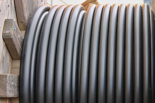
Oil-cooled Cables

Application
The application mode of the Oil-cooled cables is mainly used to connect electric vehicle charging
devices to the charging infrastructure, thus providing fast power transmission to electric
vehicles, and equipped with a certain number of signal and control lines to ensure accurate
control and safe and error-free operation of the entire charging process.
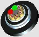
The Oil-cooled cable structure is mainly composed of the main core of power supply, ground wire,
signal wire or shield wire set, return pipe, filler and reinforcing rope combination. DC+ and
DC- conductors are immersed in the cooling medium to take away heat through the medium
and form a cooling circuit through the circulation of the return pipe, which eventually carries
a larger current with a smaller conductor cross-section to achieve the effect of high-power
fast charging. The Oil-cooled cable use scenario is generally used in centralized charging stations,
large parking lots, hotels, garages and other areas.
Standard and Approval
Basic design to IEC62893-4-2
Cable construction
Conductor: Bare copper or tinned copper, class 5 to IEC60228.
| Power cores | 16mm2 to 150mm2 |
| Control or pilot cores | min. 0.5mm2 |
| Optional PE conductor | min. 25mm2 |
| Optional auxiliary power cores | 2.5mm2 to 6mm2 |
Insulation: Irradiation cross-linked polyolefin.
Screen(optional): Braided copper wire.
Tube: Irradiation cross-linked polyolefin.
Filler: PP hemp or cotton yarn.
Tape: Non-woven fabric.
Sheath: TPU, Black,other colours can be offered upon request.
TECHNICAL CHARACTERISTICS
Temperature range: - 40º C to + 90º C
Rated voltage: AC 600V/1000V ; DC 1500V
Flame resistant: According to EN 60332-1-2
Minimum bending radius: 6×OD
Dielectric voltage: 3.5kVac/15min.No Breakdown
Oil resistant: IRM902,100°C/168h Tensile and Elongation >=60%
Cold bending: -40°C/4h No cracks
Hot shock: 150°C/1h No cracks
Crush resistant: >11KN
Weather resistant: 720min a xenon arc weatherometer, No cracks
CONSTRUCTION PARAMETERS
| No.of Cores×Cross section | Nominal Thickness of Insulation | Nominal Thickness of Sheath | Maximum Overall Diameter | Minimum Insulation Resistance at 90 °C |
| mm² | mm | mm | mm | MΩ · km |
| 2×16 | 0.8 | 2.4 | Design
structures
according to standards or customer requirements |
0.0044 |
| 2×25 | 1.0 | 2.8 | 0.0043 | |
| 2×35 | 1.0 | 3.2 | 0.0037 | |
| 2×50 | 1.1 | 3.6 | 0.0034 | |
| 2×70 | 1.2 | 4.0 | 0.0031 | |
| 2×95 | 1.2 | 4.4 | 0.0028 | |
| 2×120 | 1.3 | 4.8 | 0.0027 | |
| 2×150 | 1.5 | 5.3 | 0.0028 |
2. The number of reflux tubes according to customer requirements.
3. Cooling medium is defined by the client.